How Delay Distance and Damping Ratio affect anemometer performance

Delay Distance and Damping Ratio

Cup and vane anemometers are characterised by several technical features, which contribute to determining the quality of the measurement collected, be it wind speed or wind direction.

In this article, we will focus on those characteristics that characterise the behaviour of a wind measuring instrument during dynamic conditions, i.e. when environmental conditions change abruptly before reaching stability.

The parameter used to qualify the dynamic response of cup anemometers is the Delay Distance (dR) or Distance Constant (LU), described in the VDI 3786-2 2000 and ASTM 5096-96 standards.

The dynamic response of a vane wind direction metre is qualified by both the Delay Distance (dR) and the Damping Ratio (D) or Damping Coefficient, as described in the reference standards VDI3786-2 and ASTM 5366-96

Wind speed measurement: what to consider?

During a change in wind speed, any anemometer does not immediately detect the change because, as in any measurement process, there is a certain delay due to inertia.

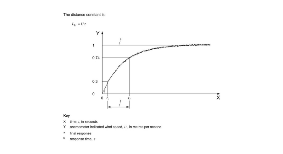
The Delay Distance is a parameter to quantify the inertia of the instrument in responding to changes in wind speed and indicates the length (in metres) travelled by a volume of wind, after a sudden change in speed, in a time equal to 63% (or a time constant τ) of the total time needed to reach the new speed.

The Delay Distance is a parameter that allows you to quantify the inertia of the instrument in responding to the variation in wind speed.

It is calculated by multiplying the wind speed by a specific time constant, obtained by considering the time interval between the moment in which 30% of the new wind speed is measured and 74% of it. This procedure is detailed in Figure 1.

La Delay Distance

Figure 1 – Trend of wind speed measurement over time (ISO 17713-1 2007 page 5)

The formula for calculating the Delay Distance is as follows:

dR= U * Ï„

With:
U: wind speed;
Ï„: time constant.

The smaller the Delay Distance, and therefore the time constant, the faster the response of the cup anemometer will be in reaching the measurement of the new speed. 

The ASTM 5096-96 standard requires that the Delay Distance be calculated for wind speed values ​​of 5 m/s and 10 m/s. In order for an anemometer to be considered accurate, the acceptable Delay Distance value should be ≤ 4…5 m (VDI3786-2).

Wind direction measurement: what to consider?

In this case, the Delay Distance represents the distance (expressed in metres) that the wind travels in the time in which the weather vane moves from its initial position to 50% of its final position, following the change in anemometric regime.

The Delay Distance value depends on the air density and is obtained by multiplying the air speed by a time constant, as in the previous case. In this case, the time constant Ï„ represents the time (in seconds) required for the weather vane sensor to move from its initial position to 50% of its final position.

For a gonio-anemometer with a good response to changes in the anemological regime, the Delay Distance should be less than 5m.

Another important parameter for the qualification of weather vane sensors is the Damping Coefficient.

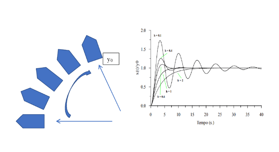
During a sudden change in wind direction, the wind vane will align along the new y0 direction. After reaching the final position, the wind vane will oscillate around y0 for a few seconds before stabilising. This oscillation will be weakly damped by air pressure.

valore della Delay Distance

Figure 2 – Schematization of the movement of the weather vane from the initial position to the final position (left); graph of weather vane oscillations over time as the Damping Ratio varies (h), with damped, undamped and weakly damped behaviour (right).

he Damping Coefficient must take values ​​D < 0.6 to ensure a weak damping of the weather vane. According to the indications of the VDI3786-2 standard, the optimal values ​​of the coefficient to maintain the weather vane in a weakly damped field are between 0.2 and 0.3.

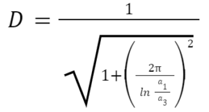
The Damping Ratio is given by the following relationship:

Damping Ratio

With:
a1: first oscillation amplitude
a3: second oscillation amplitude

Contact us for more information
Please enable JavaScript in your browser to complete this form.
Click or drag files to this area to upload. You can upload up to 6 files.
Checkbox